Mig Welding Outside Corner Joints..
1F, 2F, and 3F

Mig welding outside corner joints can be pretty easy.
especially if the weld joint is flat in front of you on a bench.
But sometimes you are given a print or drawing with welding symbols and a full penetration weld is specified with a symbol something like this
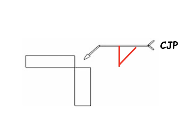
There is much discussion on what the correct weld symbol should be for an open corner joint calling for a complete penetration weld but this is one possibility that you might see as a welder in a shop trying to comply with welding symbols on a drawing.
There is a fillet weld symbol indicating the weld is to be made from the arrow side of the joint...and the cjp in the tail, indicates complete joint penetration is required.
 |
 |
 |
In the second video on this page , I gapped the pieces 1/8" in order to provide for complete penetration.
If the weld needed a certain size fillet weld on each side then a symbol on each side of the reference line would be used.
Mig Welding outside corner joint in one pass uphill
The trick here is to set the machine so that you can penetrate all the way into the root of the joint...but at the same time, not pile up big ugly convex weld... not get undercut, and not get lack of fusion in the root of the joint.
The first setting seemed ok at first but was leaving some undercut.
The second setting of around 17.4 volts and 170 ipm was better and would have worked out ok if I had time to practice to adjust my technique a bit....maybe pause at the weld toes longer and move quicker across the middle.
2 pass weld ...downhill root...uphill fill
I decided to try a 2 pass weld where I gapped the pieces around 1/8" and welded the root pass downhill at 20 volts and 200 ipm.
The root pass went in nicely but I knew I would need to lower the heat for an uphill pass.
So I set the machine to 17.8 volts and only 165 ipm wire speed for mig welding the second uphill pass.
After cutting and etching samples of each weld, It was obvious that the 2 pass weld provided a thicker cross sectional thickness of the weld.
Either weld might have been acceptable for certain criteria but the 2 pass weld was definitely a stronger weld that was less likely to fail under cyclic loading or thermal cycles.
The main thing I noticed during the cut and etch test process was the appearance of what seemed to be a lamination in the base metal.
I will need to polish this specimen to a higher level and examine under higher power magnification to determine exactly what is going on.

Would you like to get free welding videos in your inbox every week?


Tig FingersThe Real and Original TIG Finger® and XL model
Stubby Gas Lens and Pro TIG kits
2% Lanthanated, CK LaYZr, Purple, more
Our Weldmonger Stubby Gas Lens kit is the Best


