
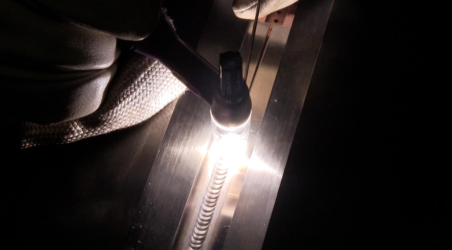
In the video above, I am TIG Welding Carbon Steel to stainless in a crude purge fixture I made over 30 years ago.
The stainless is .062” thick and the carbon steel is .040” .
A slight difference in thickness is not a big deal and I used a 1/16” diameter 312L TIG rod.
312L tig rod is very crack resistant and is great for tig welding dissimilar metals like stainless to carbon, or even for tig welding 4130 chromoly to carbon steel or high strength steel.
312L TIG rod is a great all purpose rod that works for all kinds of different steels. Its a great rod to have because if the metal is unknown but is some type of steel, 312 will probably work.
Stainless steels, carbon steels, 4130, tool steels, nickel alloys, or practically any combination of these can be joined using 312 stainless rod.
I have a really nice purge fixture made for me by ABOM79 (Adam Booth) and it works great.
In fact, I have shown it in use on several other videos on aerospace welding tests.
But just for kicks I used a very crude fixture that I cobbled together many years ago out of 1/2” plate using only a plasma cutter and a grinder.
This was the fixture I used to get started testing welders while waiting for some more precision fixtures to be made.
When you make a full penetration weld on stainless, shielding the back side with argon is necessary to avoid a condition called granulation aka “sugaring”.
A purge fixture takes care of purging the back side of the weld and holds thin pieces in place while you tack and weld.
Sometimes you might be required to tack weld both ends without a gap, but
positioning the pieces with a gap at one end might be an option.
It really just depends on the policies and procedure used. And of course the person administering the test.
In my experience, unless you really crank down on the chill bars, a 1/8” gap will close up in a 6 inch piece.
The way the gap shrinks illustrates the shrinkage stresses as a weld progresses.
Here are the details and settings used.
.062” 304L stainless welded to .040” 1018 carbon steel
10-15 cfh flow of purge gas on fixture
MK 14 cup 30-33 cfh argon
1/16” 312L filler rod
3/32” 2% lanthanated tungsten ( a 1/16" would be more common for most aerospace welding tests in the 40 amp range)
40 amps using a primeweld 225
Aerospace Welding Test and Fixture built by Abom79
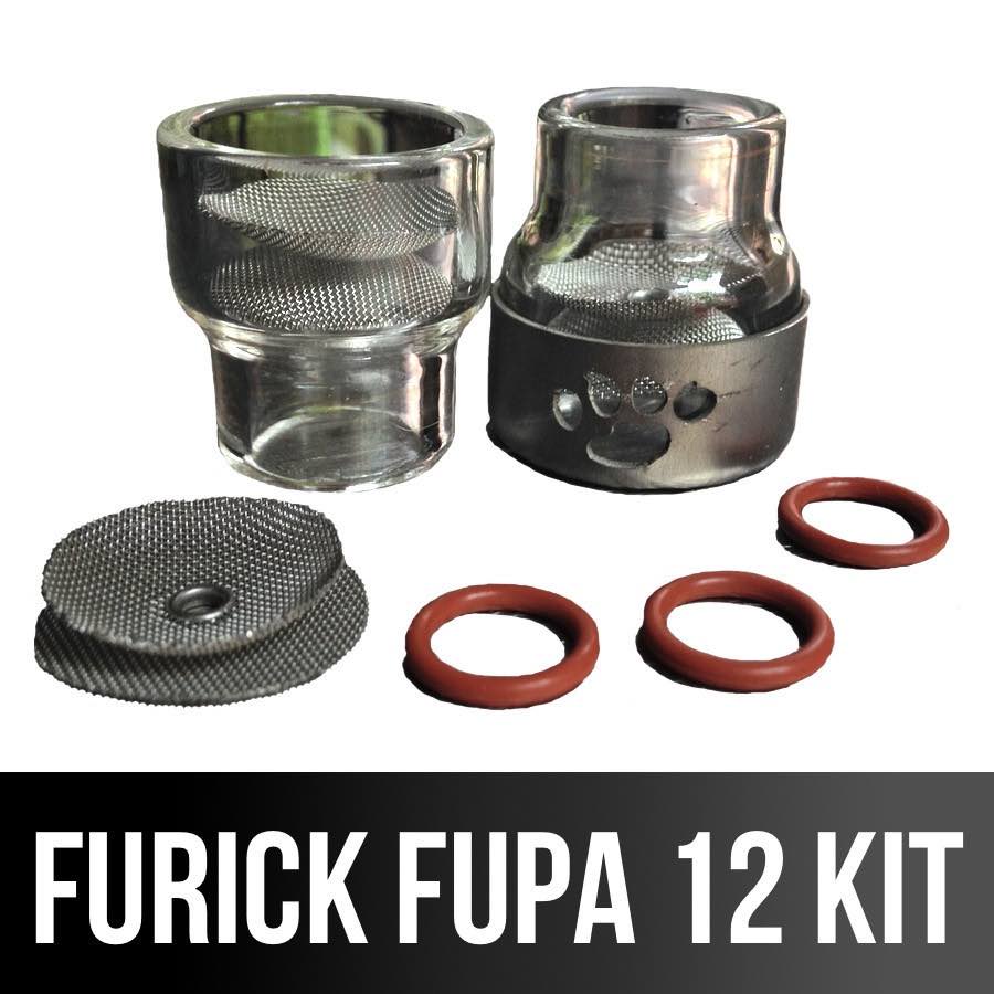
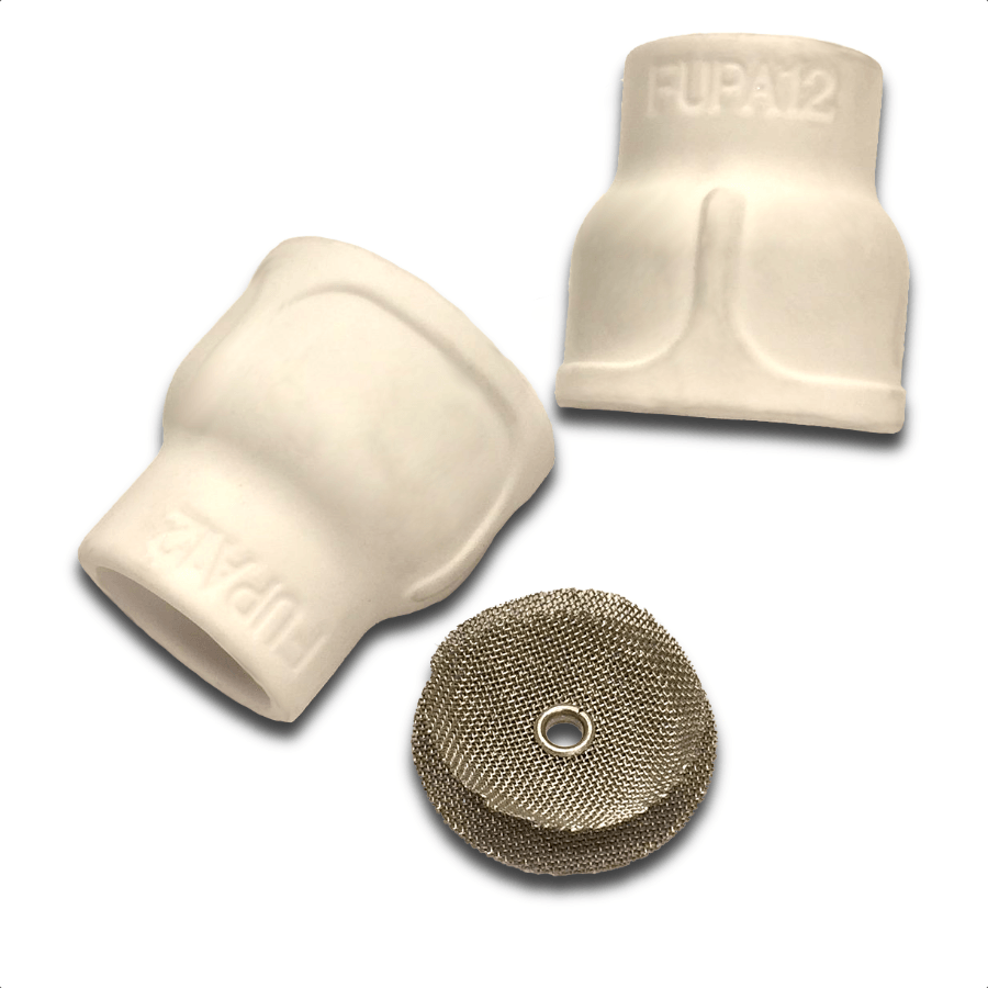
click here to learn more about the Furick ceramic 12 cup
Aerospace welding tests are usually done using a purge fixture that holds the test pieces flat using chill bars while providing argon shielding to the penetration side of the test pieces.
My friend Adam Booth (abom79 on youtube) built me this purge fixture so that I could use it for future welding videos.
Adam documented the build in a series of videos on his Abom79 channel and even made a playlist of 7 videos showing each part being made.


Why even use a fixture for an aerospace welding test? isn't that cheating?
There is no requirement to use a fixture listed in the AWS D17.1 specification.
But welding test coupons can be pretty thin and need to be held flat for x-ray testing.
The most common thicknesses are usually in the .020" - .063" range but sometimes much thinner.
It is impractical to weld something .020" or thinner without some type of fixture to hold it straight and provide argon shielding to the back side of the weld.
AWS D17.1 lists several different groups of metals commonly welded in the aerospace industry.
Carbon and low alloy steels, stainless alloys, and nickel alloys are divided into 2 sub groups. one is deemed more difficult.
Qualification in the more difficult group also qualifies for the metals listed in the less difficult sub group.
here are the main metal groups along with the commonly used test metal.
- carbon and low alloy steels - 4130
- iron based stainless steels - 17-7ph or 15-7ph
- nickel alloys - inconel 718
- aluminum alloys - 6061
- magnesium alloys - AZ31B
- titanium alloys - 6AL4V
- cobalt alloys - L605 or haynes 188
- other alloys like refractory and copper alloys ( niobium, molybdenum, tantalum)
The chill plates are adjustable to accommodate different metals thermal conductivity and different thicknesses.
For stainless and nickel alloys as well as titanium and cobalt alloys, having the chill bars very close to the bead can help the end result.
For
aluminum and magnesium, moving the chill bars out a bit farther seems
to work better by slowing the cooling rate of the weld. ( slower cooling rate can help prevent porosity)

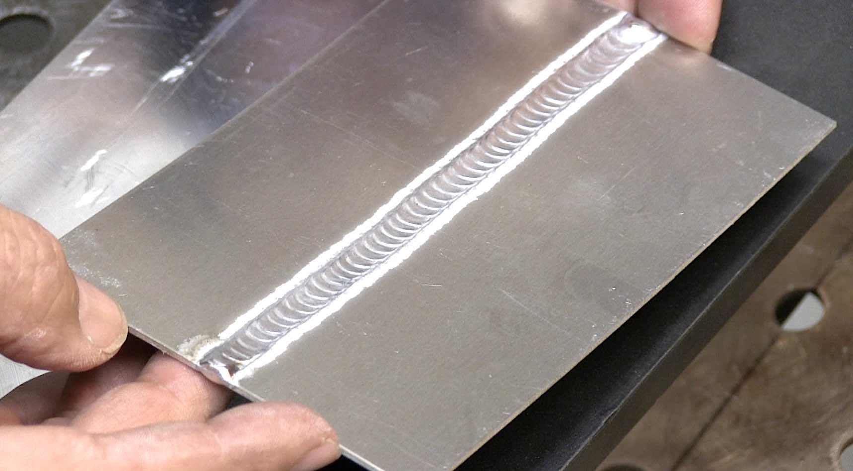
the pic below shows what I have found helps in preventing crater cracks when stopping.
...a slow tapering off the amperage while adding less and less filler

Settings for an Aluminum welding test to comply with AWS D17.1
2 settings that can make a big difference in passing an aluminum welding test are:
1. AC balance
2 AC frequency
From quite a few years of experience, I had greater success on aerospace welding tests with AC balance set to around 67% Electrode negative (EN).
In addition, it seemed that using lower frequencies helped.
So I set AC balance to 67% EN and AC frequency to 77hz
the other main difference maker is cleanliness of the metal and filler wire.
And the filing of the sheared edge makes a tremendous difference on an aerospace welding test.
interested in the drawing for the Abom79/Weldmonger back purge fixture? here it is. free of charge


Would you like to get free welding videos in your inbox every week?


Tig FingersThe Real and Original TIG Finger® and XL model
Stubby Gas Lens and Pro TIG kits
2% Lanthanated, CK LaYZr, Purple, more
Our Weldmonger Stubby Gas Lens kit is the Best


