Arc Welding

more commonly called "stick welding" Proper AWS term is SMAW shielded metal arc welding
A very common welding test joint is a 3G plate with backing

Principles of Arc Welding also known as "Stick Welding"
Electric arc welding is based on the fact, as electricity passes through a gaseous gap from one electric conductor to another, a very intense and concentrated heat is produced. The temperature of the spark or arc jumping between two conductors is approximately 6,500 to 7,000 degrees. (although the plasma created by the arc reaches temperatures in excess of 20,000f)
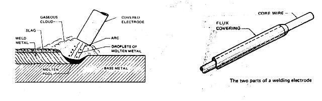
When the arc welding electrode is brought into contact with the workpiece a high temperature arc is established between them. The arc heat is controlled by current and by arc length (electrode to workpiece spacing). If they are correct, the arc heat melts the electrode tip and the workpiece beneath it to the desired depth.
If two pieces to be joined together form the workpiece, they are fused together in the puddle. Fused filler metal from the electrode reinforces the joint, forming a penetrating raised deposit of welded metal (bead) as the puddle. Fluxing materials in the heavily covered electrode will give the arc stability, help to float out impurities from within the molten puddle, and will develop inert gases which will keep the outer surfaces of the molten weld from oxidizing. The flux hardens as the weld cools, forming a crust/slag on the surface, providing a shield against contamination of the bead.
As the bead forms, the electrode (and the arc) are continuously moved ahead. The molten puddle moves with it, and filler metal continues to transfer to it. With all factors fully controlled, a smooth, continuous bead is deposited to make a well fused joint. These basic control factors are speed of electrode travel, amount of current (amperage) and length of arc (voltage).
Arc welding requires high electrode current to produce an arc of great heat. These two controllable factors (current and heat) can produce hazards when not controlled. The by-products of arc welding are fumes, ultraviolet and infrared rays, sparks and spatter are also potential hazards when not controlled.
Arc Welding Positions
arc welding
The American welding society classifies different arc welding positions with a numbering system that goes like this: 1f= flat fillet weld, 2f = horizontal fillet weld, 3f = vertical fillet weld, 4f= overhead fillet weld.
For groove welds : 1g =flat groove weld, 2g = horizontal groove weld, 3g = vertical groove weld, 4g= overhead groove weld.
To keep things simple I will just refer to the different positions as : flat, horizontal, vertical and overhead. OK?
Arc Welding in the Flat Position
There are many different types of flat welds, possibly these are the easiest type welds for a beginning welder to practice on, later advancing to the more difficult positions. One of the advantages is easier control of the welding puddle. Gravity is not much of concerning factor, because no matter what type joint you are welding, it’s always FLAT and all gravity does is help the weld lay down Flat.
Butt Joint
On material to be welded which is 1/4 inch or less in thickness, V grooving the edges usually is not necessary, depending on the strength and circumstances relating to the job. When welding material of greater thickness it is necessary to grind or cut a V-joint in the two pieces of metal, which will increase the overall strength of the weld. The two pieces should be placed touching each other with both surfaces free from paint or other contaminants which will affect the strength of the weld. After striking an arc, with proper setting of amperage control and electrode size, the arc should emit a sound (such as BACON FRYING) which indicates proper arc length and speed of electrode movement. In the case of a long weld where more than one electrode is used, the arc shall be restarted about 1/4 inch ahead of the crater. Going back over the crater to properly fill in and keep a uniform contour, thus assuring proper preheating as in the start of the weld.
Lap Joint
This type of seam is common although it is not the best weld for strength. To arc weld this joint successfully, remember that the piece which is not having its edge welded will require the greater portion of the heat. To distribute the heat, a weaving motion must be used with most of the motion taking place over the bottom piece. The electrode must be held in a position to point it at a slight angle to the joint. To keep the arc length constant, the welder must raise the electrode slightly as the arc travels over the edge of the upper piece. The finished bead should be crowned ,straight, must be even in width, smooth and clean. It should show good fusion between the bead and the parent metal
T - Joint
The t-joint is formed by placing one of the base metal pieces in the center, or near the center of the other piece of base metal and at a right angle to it, to form a T shape. This joint may be welded on one side or on both sides, depending on the thickness and strength needed for the job.
Horizontal ARC Welding
When arc welding a butt, lap, edge or outside corner joint in the horizontal position, the electrode should be pointed upward at about 20 deg. to counteract the sag of the molten metal in the crater. The electrode is also inclined about 20 deg. in the direction of travel of the weld. The arc gap (low voltage) should be shortened so the molten filler metal will travel across the horizontally positioned arc. Be sure to eliminate undercutting at the edge of the bead, which is the result of excess current for the size of the electrode used or poor electrode motion. When welding a T or inside corner joint with one piece of the base metal in a near vertical position, and one in a near horizontal position, the arc welding electrode is inclined 20 deg in the direction of travel. The arc welding electrode is also positioned at about 45 deg. angle to the horizontal piece of metal. The motion is usually some type of weave with the forward motion taking place on the vertical piece.

Vertical Up and Down Arc Welding
These welds even though more difficult than flat must be of the same strength and quality. When welding a vertical seam, the molten metal tends to flow down the seam. This flow can be minimized by pointing the electrode approximately 20 deg. upward. A short arc must be maintained, and the motion must be such that the force of the arc will oppose the sagging. This can be done by using the previously welded area to help support the crater. When welding vertical down, hold the rod at an angle of, 20 deg to the work piece. As you pass the electrode down the seam, crossing from side to side. Use pressure the arc creates to actually push the molten crater upward. This will allow time for each side to fuse together before each pass, resulting in a good strong weld. Vertical up is done in much the same way, the difference is your pass from side will be in the up position allowing the weld crater to gently flow across the previously welded material, thus supporting the weld.
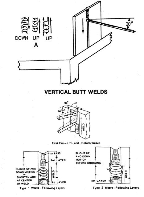
Overhead ARC Welding
To master the final and most difficult arc welding position (overhead), proceed through the practice beads, butt welds and fillet welds. Electrode positions and welding techniques are shown below. The weaving motion of the electrode is lift and return, to freeze the puddle and prevent slag drip. Always be very careful when welding in this position, to keep your shirt collar buttoned and use a welding apron to prevent any welding slag from dropping into your clothes. 2 main things that beginners struggle with is amperage and arc length. Make sure to use a close arc length (tight enough to actually “feel” the rod scrubbing against the metal) and use enough amperage so the rod doesn’t stick when your arc is that tight.

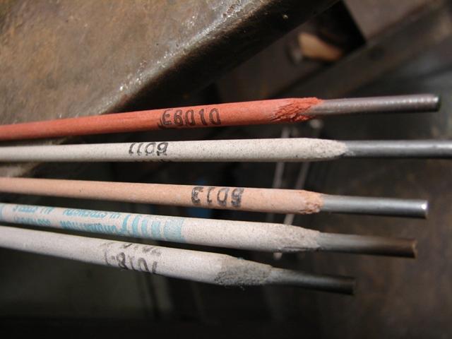
Stick Welding Electrode Identification System
Mild Steel Electrodes
Mild steel electrodes are identified by a system that uses a series of numbers to indicate the minimum tensile strength of a good weld, the position’s in which the electrode can be used, the type of flux coating, and the types of welding currents
Mild Steel welding electrodes
Mild Steel Electrodes
Mild steel electrodes are identified by a system that uses a series of numbers to indicate the minimum tensile strength of a good weld, the position’s in which the electrode can be used, the type of flux coating, and the types of welding currents.
E6012 The letter E prefixes the number and represents the electrode. The E is used as a prefix for any filler metal that uses electricity to perform a weld.
E6012 The first two or three numbers indicate the minimum tensile strength of a good weld, for example E60XX, E70XX, E110XX. The tensile strength is given in pounds per square inch (psi.). The actual strength is obtained by adding three zeros to the right of the number given. For example, E60XX is 60,000 psi. and E110XX is 110,000 psi.
E6012 Refers to the metal welding position. The number 1,2,3, or 4 to the right of the tensile strength designation gives the position...1= all positions - 2 =horizontal or flat - 3 = flat only - 4 = all positions but vertical down.
E6012 The last number indicates the major type of flux covering and the type of welding current.
0 - DCRP 1 - AC/DCRP 2 - AC/DCSP 3 - AC/DC
4 - AC/DC
5 - DCRP
6 - AC/DCRP
8 - AC/DCRP
DC = direct current
DC/SP = direct current straight polarity
AC =alternating current
DC/RP = direct current reverse polarity
Understanding Stick welding Electrode Data
Tensile Strength The load in pounds that would be required to break a section of good weld that has a cross-sectional area of one square inch.
Yield point,PSI The point in low and medium-carbon steels at which the metal begins to stretch when stress is applied, after which it will not return to its original length.
Elongation The percentage, a two inch piece of metal will stretch before it breaks.
Charpy V-notch ft.lb. The impact load required to break a test piece of welded metal. This test may be performed on metal below room temperature, at which point it is more brittle.
Stick Welding Alloy Elements and Their effects on Steel
Carbon (c) As the percentage of carbon increases, the tensile strength increases, the hardness increases, and ductility is reduced.
Sulphur (S) It is usually a contaminant and the percentage should be kept as low as possible, below 0.04%. As the percentage of carbon increases, Sulphur can cause hot shortness and porosity.
Phosphorus (P) It is usually a contaminant and the percentage should be kept as low as possible. As the percentage of phosphorus increases, it can cause brittleness, reduced shock resistance, and increased cracking.
Manganese (Mn) As the percentage of manganese increases, the tensile strength, hardness, resistance to abrasion, and porosity all increase; hot shortness is reduced.
Silicon (Si) As the percentage of silicon increases, tensile strength increases, and cracking may increase.
Chromium (Cr) As the percentage of chromium increase, tensile strength, hardness, and corrosion resistance increase, with some decrease in ductility.
Nickel (Ni) As the percentage of nickel increases, tensile strength, toughness, and corrosion resistance increase
Molybdenum (Mo) AS the percentage of molybdenum increases, tensile strength at elevated temperatures and corrosion resistance increase.
Stick Electrode Selection--Choosing the right Stick Rod
Type of Current: Can the welding power source supply AC only, DC only, or both AC and DC?.
Power Range: What is the amperage range on the welder and it’s duty cycle? Different types of electrodes require different amperage settings even for the same size welding electrode.
Type of Metal: Some welding electrodes may be used to join more than one similar type of metal. Other electrodes may be used to join two different types of metal.
Metal Thickness: The penetration characteristics of each welding electrode may differ. Selecting the electrode that will properly weld on a specific thickness of material is very important.
Weld Position: Some electrodes will weld in all positions. Other electrodes may be restricted to the flat and horizontal or vertical positions, or only the flat electrodes will weld on metal that is rusty, oily, dirty or galvanized with sufficient penetration.
No. of passes: The amount of reinforcement needed may require more than one pass. Some welding electrodes build up faster and others will penetrate deeper. The welding slag may be removed more easily from some welds than others.
Temperature: Welded metals react differently to temperature extremes. Some welds become very brittle and crack easily in low temperature service. (when welding in cold temperatures, you should pre-heat the metal, and after the weld is made it should be covered or shielded from the cold to allow it to cool slowly).
Mechanical: Mechanical properties such as tensile strength, yield strength, hardness, toughness, ductility, and impact strength can be modified by the selection of specific welding electrodes.
Distortion: Welding electrodes that will operate on low-amperage settings will have less heat input and cause less distortion. Welding electrodes that have a high rate of deposition (fills joints rapidly) and can travel faster will cause less distortion.
Welding Clean-up: The hardness or softness of a weld greatly affects any grinding, drilling, or machining. Also slag and spatter removal affects the time and amount of clean-up required.
Most Common Steel arc or stick Welding Electrodes
E6011 The E6011 electrodes are designed to be used with AC or DC reverse polarity currents and have an organic-based flux. They have a forceful arc that results in deep penetration and good metal transfer in the vertical and overhead positions. The electrode is usually used with a whipping or stepping motion. This motion helps remove unwanted surface materials such as paint, oil, dirt and galvanizing. The E6011 has added arc stabilizers which allow it to be used with AC. Using this welding electrode on AC current only slightly reduces its penetration qualities. The weld puddle may be slightly concave from the forceful action of the rapidly expanding gases. This forceful action also results in more spatter and spark during welding.
E6013 The E6013 electrodes are designed to be used with AC or DC, either polarity current. They have a rutile-based flux (titanium dioxide). The electrode has a very stable arc that is not very forceful, resulting in a shallow penetration characteristic. This limited penetration characteristic helps with poor fitting joints or when welding thin materials. Thick sections can be welded, but the joint must be grooved to allow for multiple weld passes. A thick layer of slag is deposited on the weld, but is easily removed, and may even remove itself after cooling. These electrodes are commonly used for sheet metal fabrication and general repair work. These electrodes are not designed for welding downhill and will trap slag easily. (They work well for learning to weld, but after that move on to real electrodes)
E7018 The E7018 electrodes are designed to be used with AC or DC reverse polarity currents. They have a low hydrogen based flux with iron powder added. The E7018 electrodes have moderate penetration and buildup. The slag layer is heavy and hard but can be removed easily with a chipping hammer. The weld metal is protected from the atmosphere by the slag layer and not by rapidly expanding gases. The E7018 is very susceptible to moisture which may lead to weld porosity.
E7024 The E7024 electrodes are designed to be used with AC or DC, either polarity current. They have a rutile based flux with iron powder added. This welding electrode has a deep penetration and fast fill characteristic. The flux contains about 50% iron powder, which gives the flux its high rate of deposition. The heavy flux coating helps control the arc and can support the electrode so that a drag technique can be used. The drag technique allows this electrode to be used by welders with less skill. The slag layer is heavy and hard but can be easily removed. Because of the large fluid puddle, this electrode is used in the flat and horizontal positions only.
Amperage guide for Stick welding / Arc Welding
to Help in Choosing Heat Settings for Arc Welding

I Hope this table helps you select the correct amp settings for Arc Welding
Voltage is typically only adjustable on really old stick and arc welding machines. Amperage is the main thing for arc welding on newer welding machines.
leave arc welding ...see more stick welding tips
Would you like to get free welding videos in your inbox every week?


Tig FingersThe Real and Original TIG Finger® and XL model
Stubby Gas Lens and Pro TIG kits
2% Lanthanated, CK LaYZr, Purple, more
Our Weldmonger Stubby Gas Lens kit is the Best


 Subscribe To This Site

